|
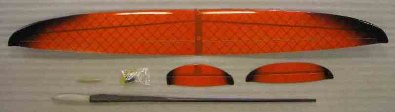
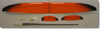
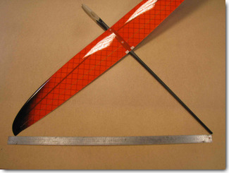
This is what you receive in the kit. Wing, fuselage, stab, fin, small parts in a bag.
Recommended radio gear:
- Wing servos - Hyperion DS09, Dymond D60
- Fuselage servos - Dymond D47
- Battery - NiMH 2/3 AAA cells or LiPo, max size 22mm x 42mm
|
|
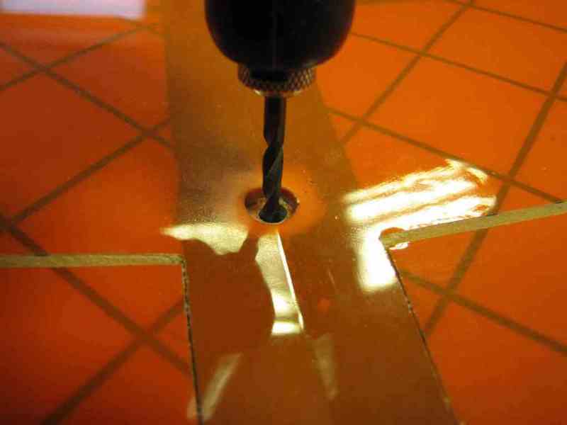
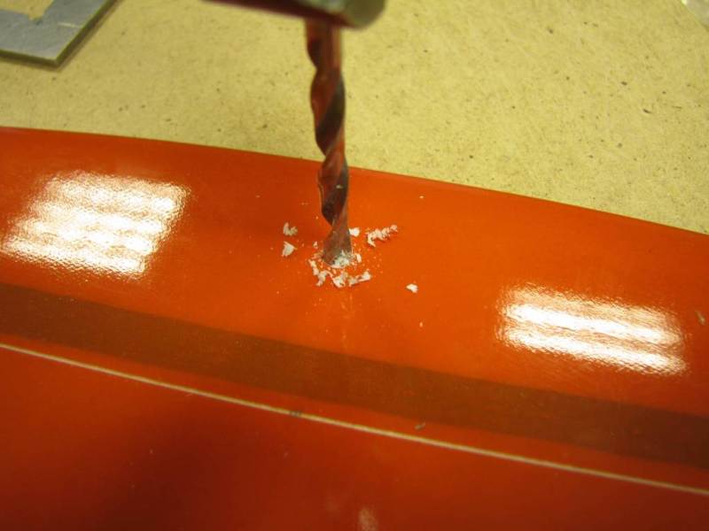
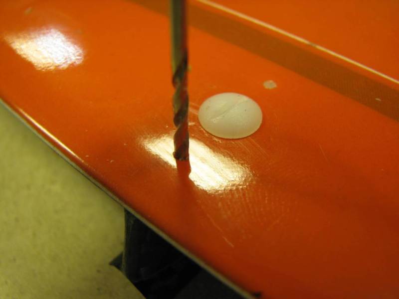
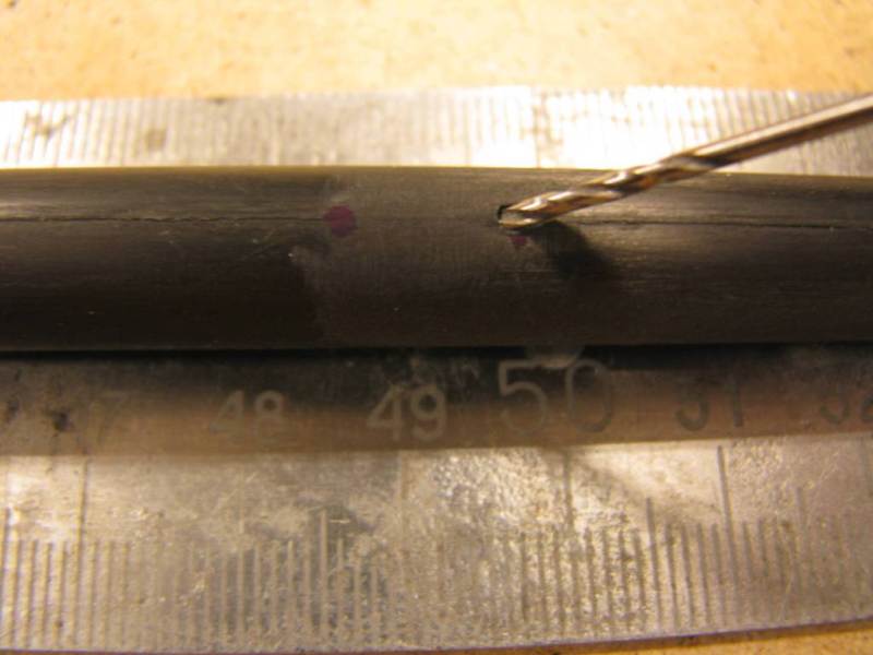
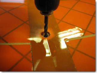
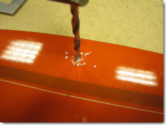
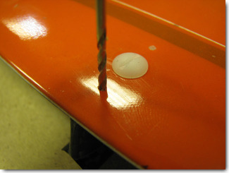
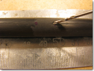
Drill the holes for wing bolts using a 4mm drill bit, in the middle of each bolt
socket.
|
|
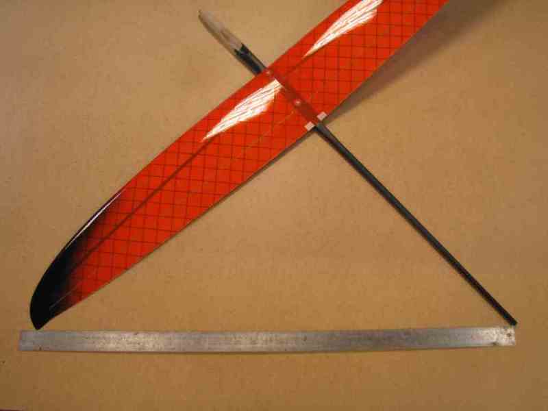
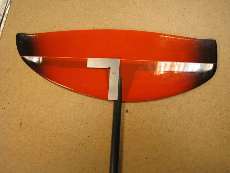
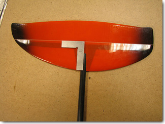
Check the wing alignment, the wing must be perfectly square to the fuselage.
|
|
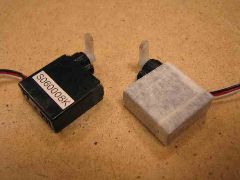
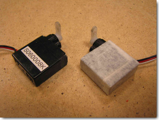
Prepare the wing servos by cutting off the mounting lugs and wrapping them in masking tape.
|
|
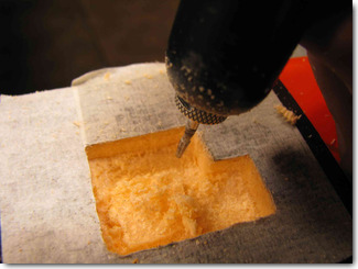
Apply masking tape to the area on the bottom wing surface where the servo pockets will be cut. Trace the servo outline about
100mm from the wing centerline, in front of the spar (behind the D-box, 50mm for new D-box wings!). Cut the pockets with X-acto knife,
then use a dremel to route the pockets to the required depth.
|
|
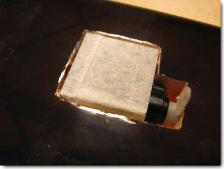
The servos must fit tightly into the pockets, flush with the wing surface.
|
|
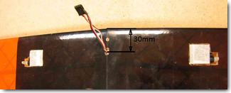
The wire channels are located at 30mm from the root leading edge (55mm for new D-box wings!). Make an exit hole for the servo
wires 30mm from the leading edge, clear the channels of the foam dust. Pull the servo wires through the
channels. Use a small amount of epoxy with microballoons to glue the servos into the
servo pockets. Do not use regular CA when working with foam. Only epoxy or foam safe
CA can be used!
|
|
Mark the location of the aileron control horn directly downstream from the
servo arm. Make a slot with a knife or a dremel cut-off wheel.
|
|
The slot for the aileron control horn must be located a couple mm from the hinge line
and must go all the way to the opposite wing skin. Glue the aileron control horn into the
slot. Do not use regular CA when working with foam. Only epoxy or foam safe
CA can be used!
|
|
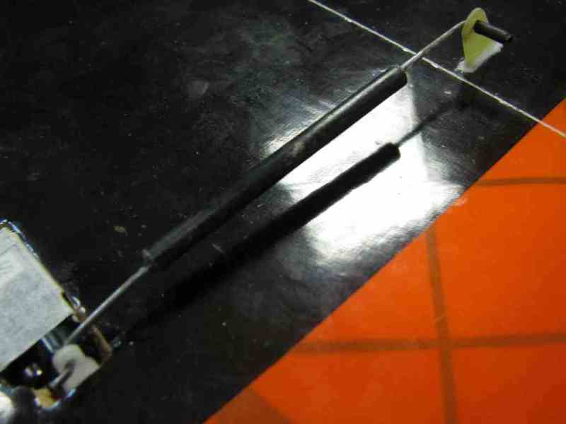
Make and install the aileron pushrod from a 1.2mm music wire. A carbon tube can be used
over the wire to add stiffness. The L-bend at the aileron horn must be fixed with
a heat shrink tubing and some CA glue.
|
|
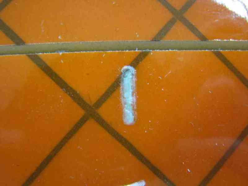
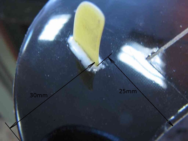
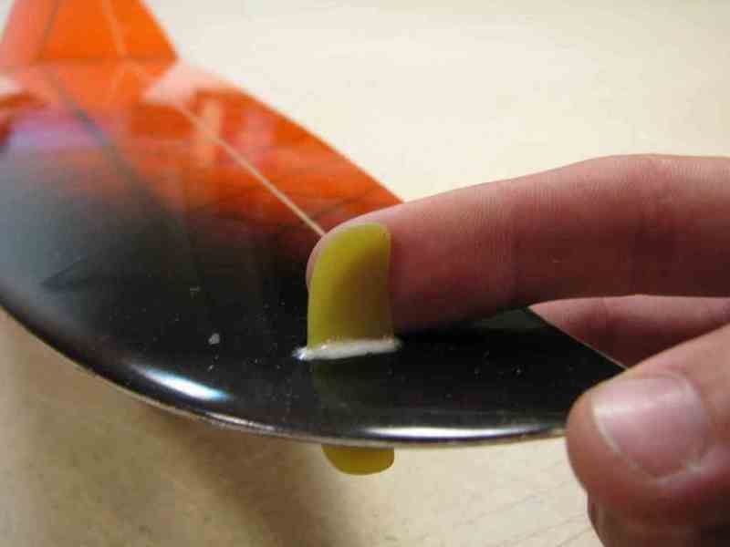
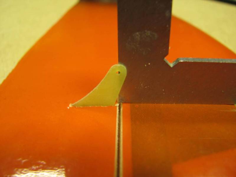
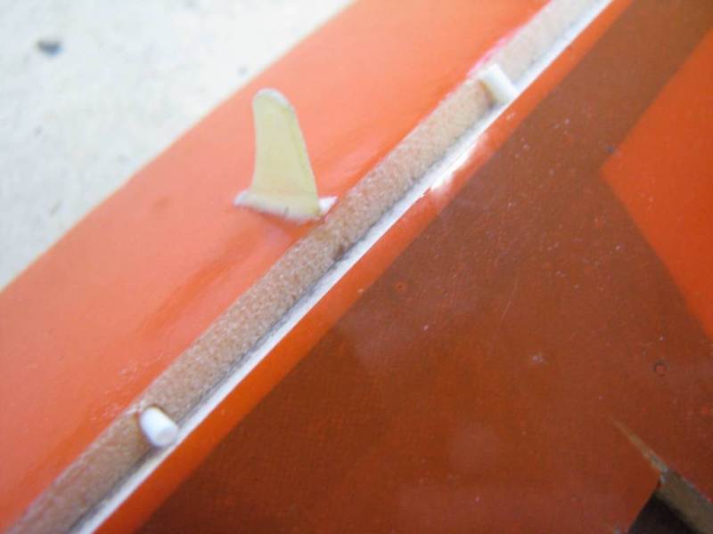
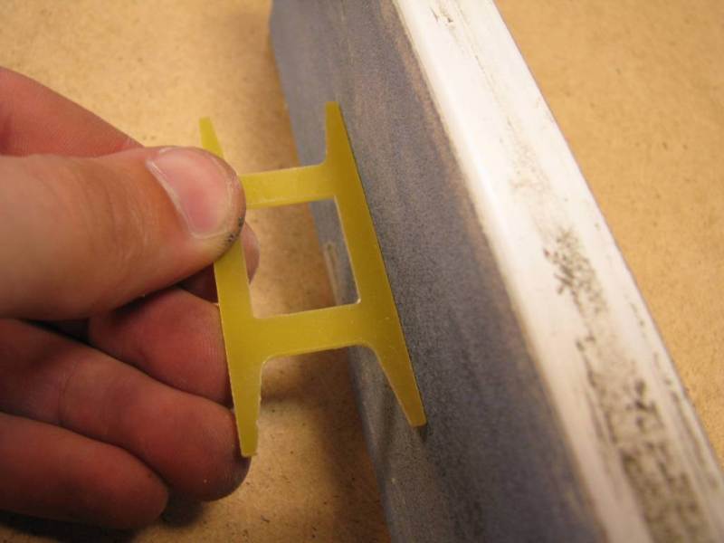
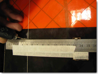
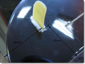
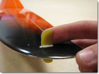
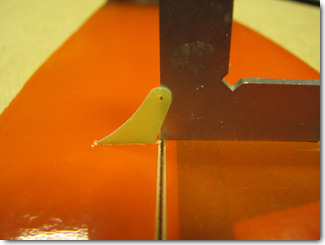
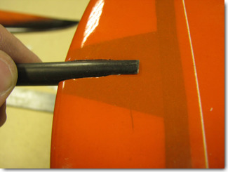
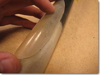
Round the edges of the throwing peg with sandpaper. Roughen the center part of the peg
for good adhesion. Make a slot in the wing approximately
30mm from the wing tip and 25mm from the trailing edge. Glue the throwing peg into the slot
with epoxy. Make fillets of epoxy around the peg for extra strength.
|
|
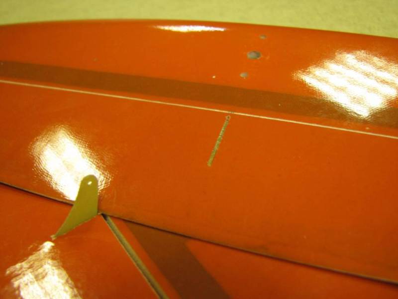
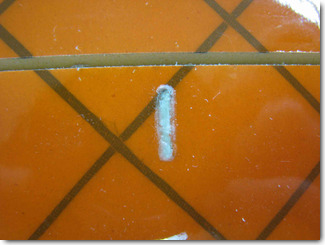
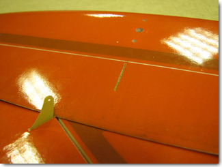
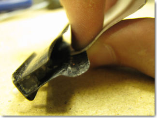
Check the peg attachment after the epoxy cures completely. Notice the epoxy fillets near the base of the peg.
|
|
The stab has epoxy hard points for the attachment bolt and fixing pins. Drill a 4mm hole for the
main bolt.
|
|
Mark and drill 2mm holes for the anti-rotation pins. Check the stab alignment with the tail boom.
Glue the pins into the stab pylon such that they do not protrude above the stab surface when
installed.
|
|
Make a slot and glue the control horn into the rudder 120mm from the bottom.
Do not use regular CA when working with foam. Only epoxy or foam safe CA can be used!
|
|
Install the elevator control horn on the centerline of the elevator. Control horns must be attached both
to the top skn and to the opposite skin.
Do not use regular CA when working with foam. Only epoxy or foam safe
CA can be used!
|
|
The recommended tail constrol system is with a pull string and a torsion spring, for both the elevator and the rudder.
Prepare a U-bracket (torsion spring) for each control surface from a 0.3-0.5mm music wire, with legs
approximately 10mm-70mm-10mm. For installng the torsion spring, drill 1.5-2mm holes in the stab and elevator.
Glue heat shrink tubing pieces into the holes. The torsion spring legs are then inserted into the tubing.
|

|
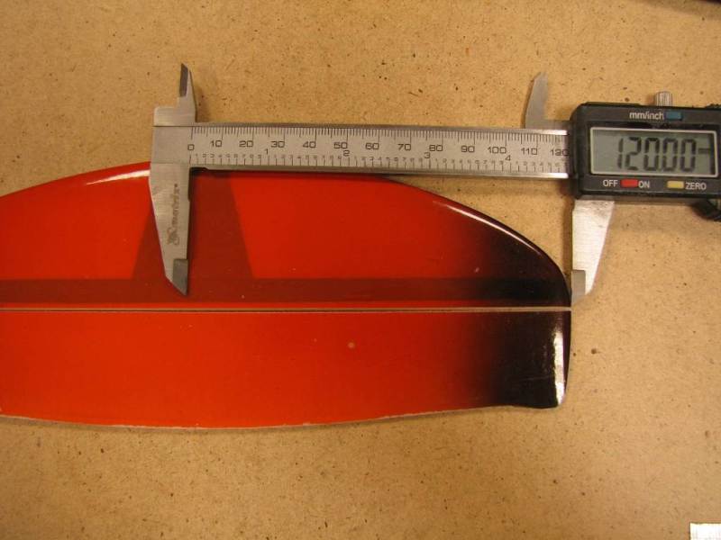
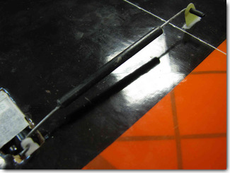
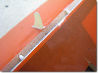
The tail boom is attached to the fin at 120mm from the bottom. Mark the centerline of the tail boom on the fin.
|
|
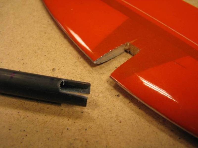
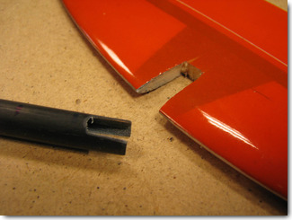
Make a 10mm deep slot in the tail boom and a 20mm deep slot in the fin.
|
|
Make sure the fin is perpendicular to the wing.
Sand the tail boom lightly around the gluing area. Do not sand the fin to avoind damaging the skin too much.
|
|
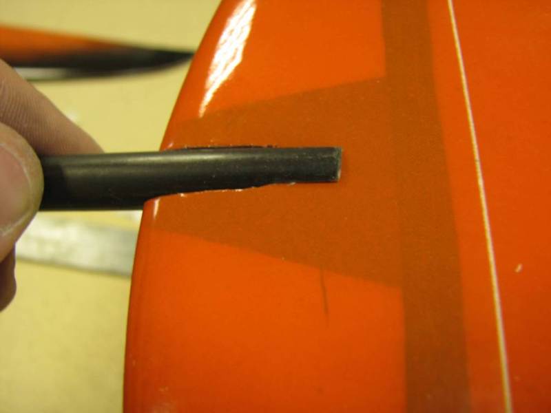
Before you glue the fin permanently, mark the location of the stabilizer pylon on the boom, and make an exit
hole for the elevator control string under the stab pylon. Angle the drill bit a little or make an
elongated hole with a micro file.
|
|
Glue the fin to the tail boom, making sure that it is square to the boom and to the wing.
Do not use regular CA when working with foam. Only epoxy or foam safe CA can be used!
|
|
Sand the inside of the stab pylon and the gluing area on the tail boom. Glue the pylon to the tail boom with epoxy or
CA, making sure that the stab is square to the fin and the wing.
|
|
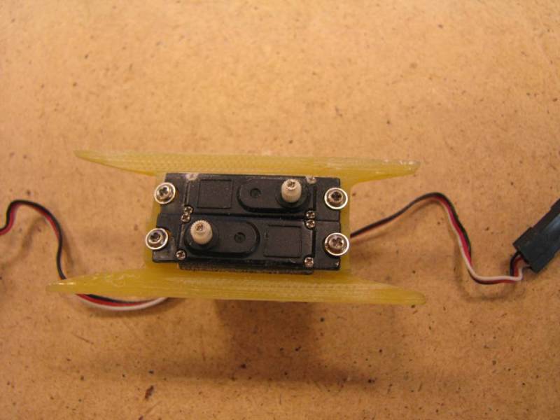
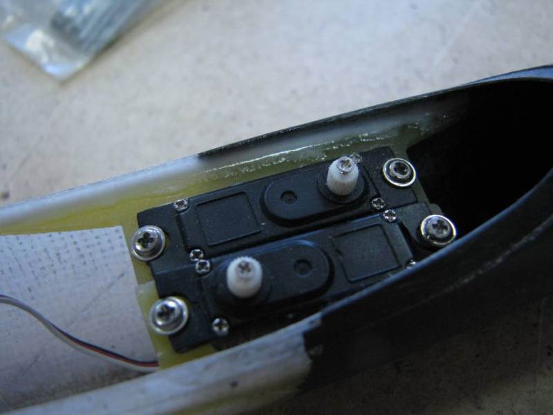
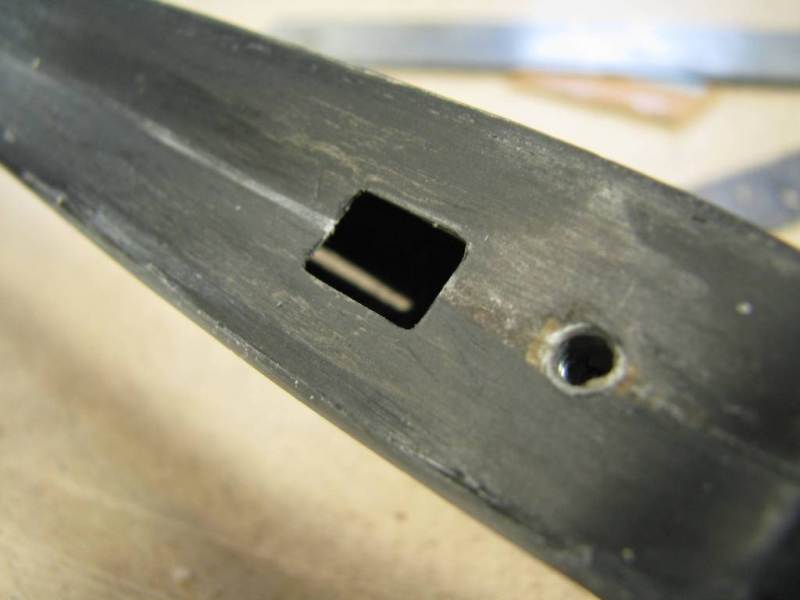
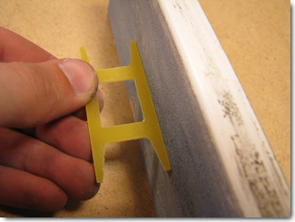
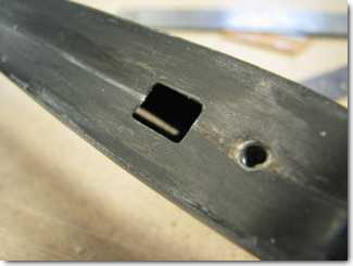
Trial fit and sand the servo platform sides if needed. It must fit tightly into the fuselage but not too tight or
the fuselage will be distorted by the internal forces. Roughen the sides a little for better adhesion.
|
|
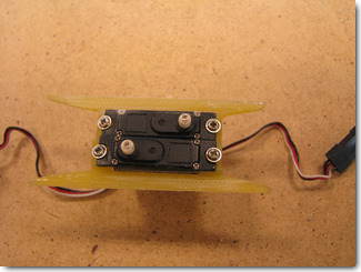
Attach the servos to the servo tray.
|
|
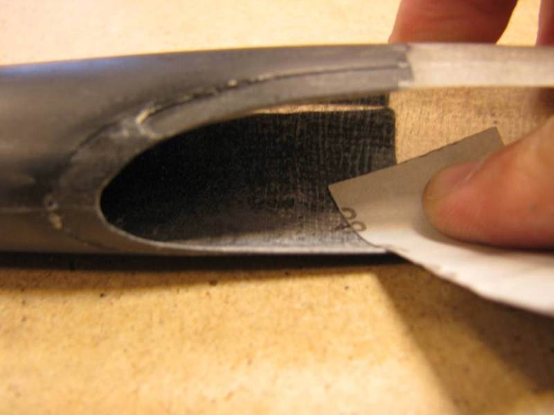
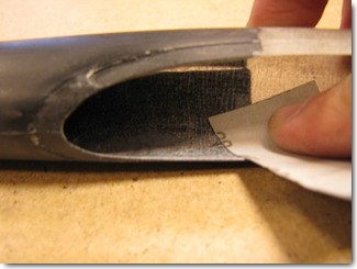
Roughen the fuselage walls where the servo tray will be glued.
|
|
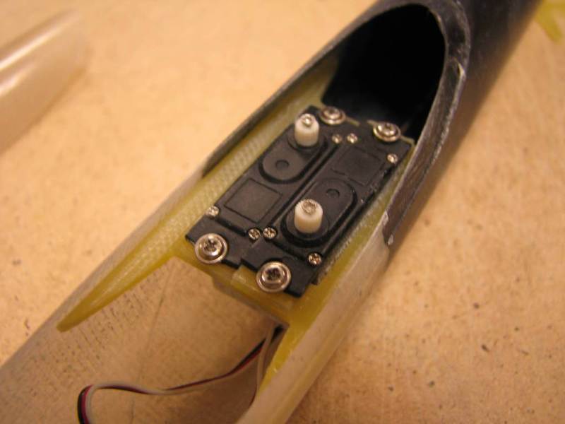
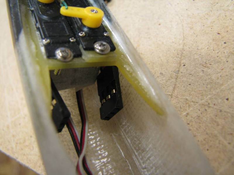
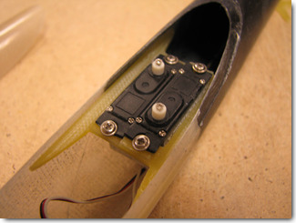
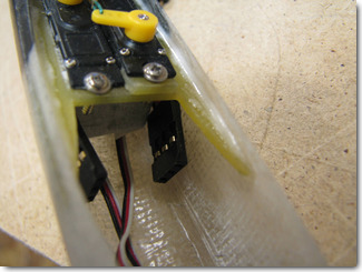
Trial fit the servo tray with servos installed.
|
|
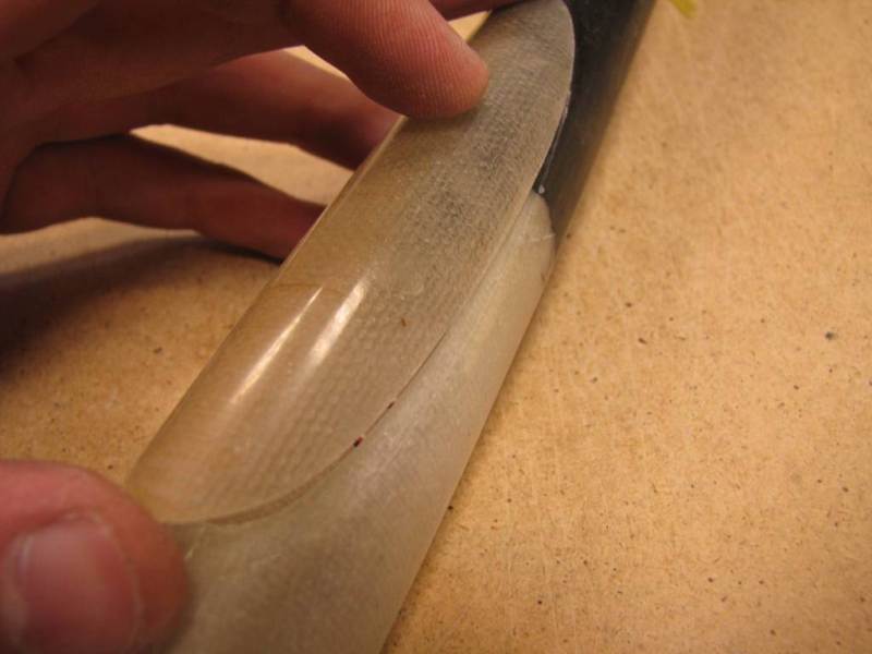
Make sure the canopy can be easily closed without interfering with the servos.
|

|
Glue the servo tray to the fuselage walls with epoxy.
|
|
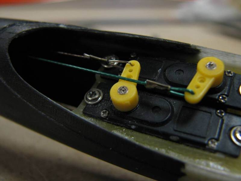
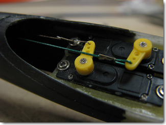
A good pull string can be made from a coated metal finishing leader material, or from a
kevlar fishing line (no stretch). First, insert the strings through the holes at the rear end
of the tail boom. Attach the front ends to the servo arms. Then stretch the strings and attach the
rear ends to the control horns.
|
|
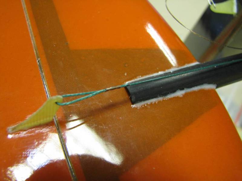
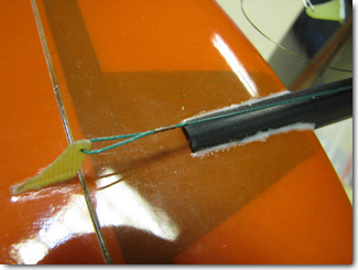
The rudder string exit hole must be made 20-30mm in front of the fin leading edge. For anchoring the
string to control horns you can use a tiny piece of a metal tube.
|
|
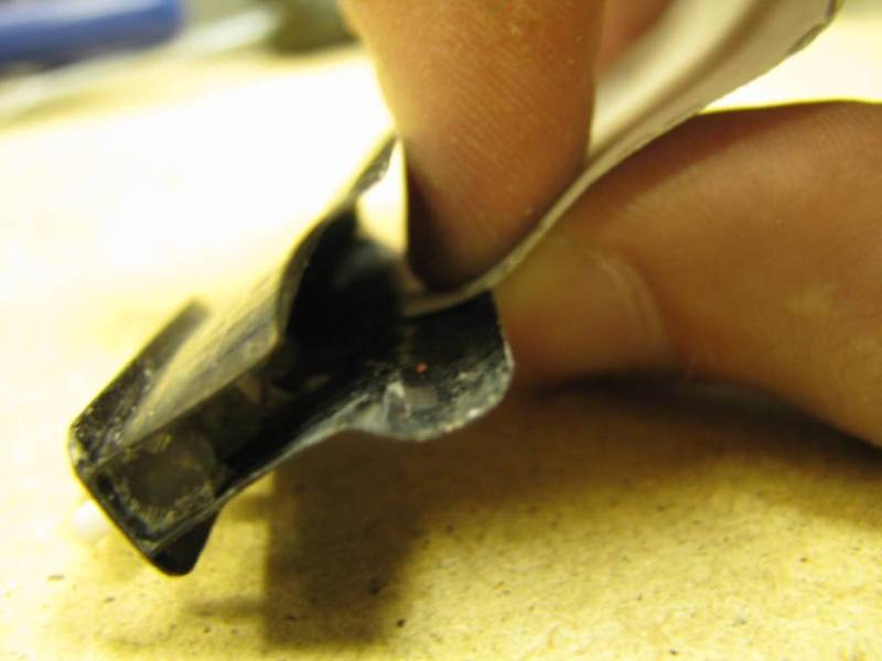
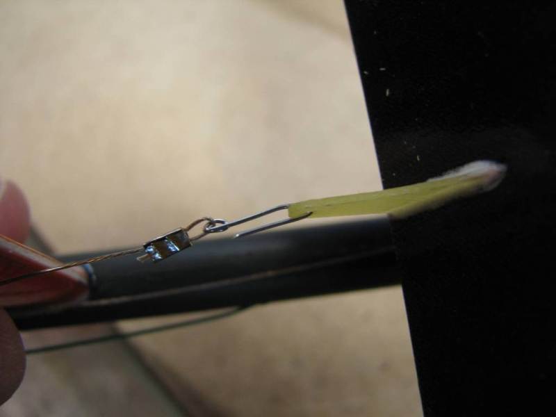
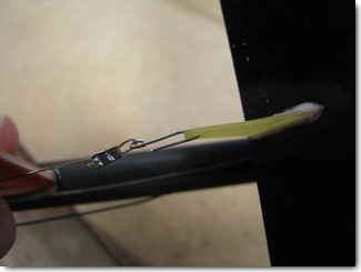
To make the elevator string easily detachable, you can use a wire hook as shown here.
|
|
Make a neat hole in the wing saddle for the wire harness.
|
|
The wire harness ends must be routed inside the fuselage on the sides of the servos. Install your battery,
receiver, and switch (if used), then check the CG of the model.
|